GB专利No.121,561
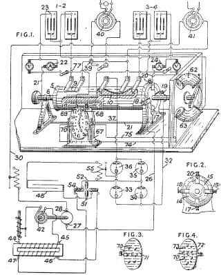
Benitez, C. April 10, 1918. Systems of charging and discharging galvanic batteries.-In an electric supply system comprising two sets of galvanic batteries, one set discharges to perform useful work and to charge the other set by means of an oscillatory circuit and a set of rectifiers. The battery connexions are varied by a commutator operated by solenoids, the circuits of which are controlled by a clock. In the position shown in Fig. 1 the commutator 5, mounted on a shaft 6, establishes the following discharging circuit for the battery 1-2-positive pole of battery, ammeter 22, lead 21, terminal 17, Figs. 1 and 2, segment 14, terminal 18, lead 26, motor 27, 28, lead 30, load 40, terminal 39, brushes and segment 9 of commutator 5, terminal 77 to negative pole of battery 1-2.; The motor 27, 28 drives an alternator 42 connected to the terminals 44, 45 of the primary winding of a transformer. The terminals 46, 47 of the secondarv winding of the transformer are connected to a condenser 48 forming with an inductance 55 and an arc 51, 52 an oscillatory circuit, which operates as a source of energy to charge the battery 3-4 through rectifying valves 33, 34, 35, and 36 and the following circuit, lead 32, terminal 19, Figs. 1 and 2, segment 15, terminal 20, ammeter 24, battery 3-4, brushes and connexion 10 of commutator, and lead 37. After a pre-determined time, the commutator 5 is operated to place the battery 3-4 on discharge through the load 41 and motor 27, 28, and to place the battery 1-2 on charge from the oscillating circuit.; The commutator 5 is operated by a handle or electro-magnetically by one of two solenoids 62, 63, the circuits of which are controlled by a clock 67. The minute hand of the clock is adapted to engage contacts 68, 69, and the hour hand is adapted to engage twelve studs 70. Six of the studs 70 are placed upon a metal disk 72, Fig. 4, provided with six holes through which the six other studs 70 on the disk 71, Fig. 3, pass. The disks 71 and 72 are connected respectively to solenoids 62, 63, Fig. 1, by leads 74, 75. In the position shown, the solenoid 62 is energized from one-half the battery 3-4; while one hour later the solenoid 63 is energized from one-half the battery 1-2 to change the position of the commutator. Specification 14311/15, which describes a battery charging and discharging system, is referred to.
标题:电能产生的新进程。
申请号:GB19180006131 19180410
出版号:121561(a)
Application Date: 1918-04-10
出版日期:1918-12-24
发明人:Benitez Carlos
受让人:Benitez Carlos
IPC: H02J 07/02
Drawing
23.储存电池库1 - 2
25.蓄电池库3 - 4
26. Direct current output
27. Electrical connection to direct current motor
28.电气连接到直流电动机
29.电机电流控制
32.负输出到负电池端子和负输入负载。
3.3.。Mercury-vapor rectifier
3.4.。Mercury-vapor rectifier
35.汞蒸汽整流器
3.6. Mercury-vapor rectifier
42.通过直流电动机轴联接的交流发电机
43.电感电阻调谐线圈
44.电气接触到升压变压器的初级线圈
4.5. Electrical contact to primary coil of step-up transformer
46.与升压变压器的次级线圈电接触
47.与升压变压器的次级线圈电接触
4.8.。Switching relay
49.与电容板的连接
50. Connection to capacitor plate
51. Carbon electrode
52. Carbon electrode
53.火花吹出线圈
54. Spark blow-out coil
55.可变电阻
78.可调滑动触点
Download PDF version of this patent

